
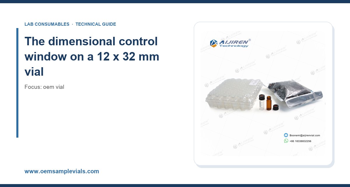
I spent eleven years on the production side of a vial plant, and the thing that surprised me most when I moved into procurement was how little buyers knew about what happens between “resin delivered” and “case shipped.” Most people picture a molding machine spitting out glass and someone putting lids on. The reality is that a vial factory floor is a chain of controlled variables, and the factory’s real job is holding those variables inside a window tight enough that your autosampler doesn’t care which lot it’s pulling from. This piece walks through what an OEM vial line actually controls, station by station, with the numbers that matter when you audit a supplier or write a spec.
The 12 x 32 mm vial is the workhorse format for HPLC autosamplers, and the tolerances on it are tighter than most people assume. The relevant reference is the GPI 12-425 thread finish (Glass Packaging Institute), which defines the thread profile, the neck finish diameter, and the sealing surface geometry. A factory that is serious about OEM work holds the following:
- Outer diameter: 12.00 mm nominal, held to ±0.15 mm. Drift beyond that and you get autosampler gripper failures on carousel-style handlers.
- Height: 32.00 mm nominal, held to ±0.20 mm. Height variation is the silent killer of needle depth consistency.
- Neck finish: GPI 12-425, with the sealing bead flatness checked on an optical comparator every two hours.
- Bottom concentricity: within 0.10 mm TIR. A vial that wobbles in the nest will draw air on a bottom-sensing needle.
- Wall thickness: 1.00 mm nominal, held to ±0.08 mm.
I have seen a plant lose a six-figure contract because height drifted to ±0.35 mm over a three-week run. The customer’s autosampler was a fixed-height carousel type, and the needle started bottoming out on the tallest vials and drawing air on the shortest. Nobody caught it because the Cpk on height had never been charted. If your supplier cannot show you a control chart for height and OD with a Cpk above 1.33, you are buying a lottery ticket.
Why the sealing bead matters more than the thread
Everyone focuses on the thread. The thread just holds the cap down. What actually seals is the annular bead at the top of the neck, the flat ring the septum compresses against. That bead has to be flat to within 0.05 mm across its full circumference, with no tooling marks, no chips, and no mold parting line running through it. I have pulled vials off a line where the bead had a 0.08 mm step from a worn mold insert, and every one of them leaked under a 1.5 bar pressure decay test. The plant’s answer was to add a silicone liner. The right answer was to replace the insert.
When you evaluate a factory, ask for the bead flatness data, not the thread gauge data. The thread gauge is easy to pass. The bead is where the real process control lives.
Resin and glass: what the line actually verifies
Most OEM vials in the chromatography market are borosilicate glass, either Type I (borosilicate 3.3) or Type II (soda-lime treated). USP <660> defines the hydrolytic resistance classes, and the factory should be running the powdered glass test on incoming lots. The numbers I look for:
- Type I borosilicate: hydrolytic resistance per USP <660> Type I, with alkali release below 0.1 mL of 0.01 M HCl per gram of glass.
- Coefficient of thermal expansion: 3.3 x 10⁻⁶ /K for borosilicate 3.3. This matters if your method involves any thermal cycling.
- Extractables: the factory should have a baseline extractables profile from a validated leachables study, typically run per USP <1663> or the PQRI working group framework.
On the polymer side, if you are buying PP or PE vials, the incoming resin certificate is not enough. The line should be verifying melt flow index on each lot, because MFI drift changes the crystallinity and that changes the solvent resistance. I once traced a batch of vials that swelled in acetonitrile to an MFI that had drifted 18% above the certificate value. The molder had switched resin suppliers mid-run to save $0.004 per part.
For a deeper look at how closures interact with these glass and resin choices, the vial closures resource covers septum and cap material selection in detail.
Molding and forming: the parameters the line holds
Whether the vial is molded or formed from tubing, the line controls a specific set of parameters. On a tubing-conversion line (the dominant process for borosilicate vials), the key variables are:
- Forming temperature: 1,150 to 1,250 °C at the neck forming station, held to ±15 °C.
- Annealing tunnel profile: a controlled cool-down from 560 °C to below 100 °C over 20 to 30 minutes, with the strain point (around 515 °C for borosilicate 3.3) crossed slowly enough to avoid residual stress.
- Residual stress: checked with a polariscope on a sampling basis. Visible stress bands in the neck region mean the annealing profile is wrong, and those vials will crack under crimping torque.
- Dimensional gauging: laser micrometers at the forming station, with SPC limits set at ±2 sigma and a hard reject at ±3 sigma.
On an injection-molding line for PP vials, the parameters are cavity pressure (typically 400 to 800 bar), melt temperature (210 to 240 °C for homopolymer PP), and cooling time. Cavity pressure is the one most plants under-instrument. Without cavity pressure sensors, you cannot tell which cavity is drifting, and a 16-cavity tool with one bad cavity will produce a 6% defect rate that looks like random noise on the outgoing QC.
The annealing tunnel is where cheap vials are made
I have walked through plants where the annealing tunnel was running at 40% line speed to hit throughput, which means vials were exiting at 180 °C instead of 90 °C. Those vials looked fine. They passed dimensional QC. They failed in the field, three weeks later, when customers crimped them and the necks cracked. The failure mode is delayed and distributed, which is the worst kind. Ask your supplier for the annealing tunnel temperature log for the last 30 days. If they cannot produce it, assume the tunnel is being run for speed.
Cleaning and depyrogenation: the numbers that count
For vials destined for regulated analytical work (pharmaceutical QC, EPA methods, clinical), the cleaning line is as important as the forming line. The factory should be running:
- DI water rinse: resistivity above 18.0 MΩ·cm at 25 °C, with the final rinse water tested for TOC below 500 ppb.
- Depyrogenation: a validated dry-heat tunnel at 250 °C for a minimum of 30 minutes, achieving a 3-log reduction in endotoxin. The validation should be per the U.S. EPA SW-846 framework for method validation where applicable, or per USP <1228> for pharmaceutical applications.
- Particle counts: less than 100 particles per vial above 10 µm, tested per USP <788> light obscuration.
- Residual moisture: below 0.1% after the dry cycle, verified by Karl Fischer on a sampling basis.
I have seen a plant skip the TOC check on the final rinse water for six months because the meter was out for calibration. The vials passed visual inspection. They failed a customer’s gradient HPLC baseline test with a rising baseline at 210 nm. The culprit was trace organics from a degraded resin in the rinse loop. That is the kind of failure that costs a supplier a customer quietly, without a formal complaint.
If you are evaluating a supplier’s analytical capability, the analytical testing resource covers the test methods and acceptance criteria in more detail.
Closure assembly and torque control
Most OEM vials ship with the closure already applied, either loosely attached (for customer removal before filling) or fully torqued (for pre-filled formats). The line controls this with a torque tester, and the numbers matter:
- Application torque for 12 mm screw caps: 0.4 to 0.6 N·m (approximately 3.5 to 5.3 in-lb). Below 0.4 N·m and the cap backs off in transit. Above 0.6 N·m and you cold-flow the septum, which changes the seal geometry.
- Removal torque: should be 60 to 80% of application torque. If removal torque is higher than application torque, the thread is galling or the cap is cross-threading.
- Crimp cap crimp diameter: 11.00 to 11.20 mm for a standard 11 mm crimp finish, checked with a go/no-go gauge.
The torque tester is one of the most commonly neglected instruments on a vial line. I have found torque testers running 15% out of calibration because nobody had sent them out in two years. Every cap on that line for those two years was either over- or under-torqued by the same 15%. That is 40 million vials with a systematic seal problem.
Septum selection is a line decision, not a catalog decision
The factory controls which septum goes on which vial, and that decision has consequences. A silicone/PTFE sandwich septum (the standard for HPLC) has a puncture life of about 3 to 5 injections before coring becomes a risk. A pure silicone septum handles more punctures but has higher extractables. A butyl septum is for GC headspace and should never be used for HPLC because the rubber leaches into the mobile phase.
If your supplier is substituting septum materials without telling you, your method is at risk. I have seen a supplier swap a PTFE-faced silicone septum for a straight silicone septum to save $0.02 per unit, and the customer’s method developed a ghost peak at 4.2 minutes within two weeks. The fix was $0.02. The investigation cost $40,000.
In-process and outgoing QC: the sampling plan
A factory that controls its line does not rely on outgoing inspection alone. The sampling plan should look like this:
- In-process dimensional check: every 30 minutes, 10 vials per cavity, measured on a vision system with SPC charting.
- Visual defect check: 100% automated vision inspection for chips, cracks, and foreign matter, with a human AQL audit at 0.65% AQL per ANSI/ASQ Z1.4.
- Functional seal test: pressure decay or dye penetration on a sampling basis, typically 30 vials per shift.
- Outgoing certificate of analysis: lot-specific, with the actual measured values, not just “pass.”
The COA point is where I see the most supplier games. A COA that says “dimensional: pass” tells you nothing. A COA that says “height: 32.04 mm, OD: 12.02 mm, bead flatness: 0.03 mm, torque: 0.48 N·m” tells you the line was in control. Demand the second kind. If the supplier pushes back, that is your answer about their process control.
Comparison: what to look for at three supplier tiers
Here is a decision checklist I use when qualifying a supplier. The numbers are the ones I have found to separate a real OEM line from a repackager.
| Control point | Tier 1 (true OEM line) | Tier 2 (contract molder) | Tier 3 (repackager) |
|---|---|---|---|
| Height Cpk | > 1.67, charted | 1.0 to 1.33 | Not measured |
| Bead flatness | < 0.05 mm, optical comparator | < 0.10 mm | Visual only |
| Annealing tunnel log | Available, 30-day history | Available on request | Not available |
| Torque tester calibration | Within 6 months, NIST-traceable | Within 12 months | Unknown |
| Final rinse TOC | < 500 ppb, logged | < 1,000 ppb | Not tested |
| COA format | Lot-specific measured values | Pass/fail | Generic |
| Change notification | 30 days, written, for any material change | Sometimes | None |
The single most predictive item on that list is the change notification clause. A supplier that will not commit to 30-day written notice for material changes is telling you they reserve the right to substitute. That is the failure mode that has cost me the most money over the years, and it is entirely preventable with a contract clause.
Troubleshooting checklist for incoming lots
When a lot misbehaves, work through this in order. I have used it on hundreds of investigations and it catches the cause about 80% of the time in the first three checks.
- Check the height distribution first. Measure 30 vials with a calibrated caliper. If the standard deviation is above 0.10 mm, the forming station is drifting and the autosampler will draw air on the tall end.
- Check the bead with a magnifier and a straight edge. Look for a step, a chip, or a parting line. A 0.05 mm step will leak under pressure.
- Check the septum thickness and durometer. A 1.0 mm PTFE-faced silicone septum should measure 1.00 ± 0.05 mm and 45 to 55 Shore A. A 0.8 mm septum will core after 2 injections.
- Run a blank injection on your own system. A ghost peak that appears at a consistent retention time across lots points to extractables. A peak that moves points to the injection process.
- Check the torque on the cap. Use a calibrated torque tester. Anything outside 0.4 to 0.6 N·m is a seal risk.
- Check for residual stress with a polariscope. Visible stress bands in the neck mean the annealing profile is wrong.
If all six pass and you still have a problem, the issue is probably your method, not the vial. I have seen more methods blamed on vials than vials blamed on methods, but the ratio is closer to 60/40 than most people admit.
What the line controls that the catalog does not show
The catalog shows you a vial. The line controls the Cpk on height, the bead flatness, the annealing profile, the rinse water TOC, the torque calibration, the septum durometer, and the change notification discipline. Those are the variables that determine whether your method runs the same on lot 1 and lot 50.
If you are sourcing for a regulated method, ask for the control charts, not the catalog. Ask for the annealing log, not the spec sheet. Ask for the torque calibration certificate, not the ISO certificate. The factory that can produce all three is the one that will still be your supplier in five years. The one that cannot is the one that will substitute a septum and cost you a method transfer.
For a starting point on the vial formats themselves, the OEM vial catalog and the chromatography vial resource cover the standard formats and finishes. For instrument-specific compatibility, the Agilent chromatography consumables and Thermo Fisher chromatography and sample handling pages list the dimensional requirements for their autosamplers, and the Restek technical resources have useful guidance on septum selection and injection technique.
The short version: a vial factory that controls its line will show you the numbers before you ask. A factory that controls only its shipping dock will show you a catalog. The difference shows up in your chromatograms about six weeks after the first shipment, and by then you have already run the samples.
References & further reading
Related resources from our lab consumables network:
- Oem Vial at oemsamplevials.com
- Vial Closures at vialclosures.com
- Analytical Testing at labanalyticaltesting.com
- Chromatography Vial at chromvials.com
External references and standards: